

The Phone.com Connector enables you to incorporate WAP (wireless application protocol) technology into BusinessWare solutions and extend applications to wireless users. With the Phone.com Connector installed, configured, and running as part of a BusinessWare solution, system administrators, business analysts, or other end-users can receive notifications of important BusinessWare events directly on their mobile phones or other hand-held wireless devices, specifically, those devices that support Openwave's Phone.com UP.Link platform. This document gets you started using the Phone.com Connector.
1.0 Overview
1.1 WAP Architecture
1.2 Openwave WAP Products
1.3 Usage Scenarios for the Phone.com Connector
2.0 Configuring the Phone.com Connector
2.1 Overview
2.2 Creating a Connection Model from the Template
2.2.1 Creating a Channel
2.3 Configuring the Flows in the Connection Model
2.3.1 Configuring the Phone.com Target Flow Properties
2.3.2 Configuring the Multi-threaded Subscriber Flow Properties
2.3.3 Notification Events
2.3.4 Connection Model Settings
2.4 Configuring the Error Model
2.5 Configuring Events and Event Processing
2.6 Registering, starting, and stopping the Connection Model
2.7 Testing the Connection Model
2.7.1 Setting up the Openwave UP.Simulator
2.7.2 Vitria Test Tool for Phone.com Connector4.0 Troubleshooting
4.1.1 Re-registering the COM-Java Bridge
The Phone.com Connector provides connectivity from a BusinessWare application to a wireless device that supports the wireless application protocol (WAP) architecture. Promulgated by the WAP Forum, WAP is an approach for transmitting web-based data to wireless devices that is based on existing Internet and W3C standards, such as TCP/IP and XML. Network and Internet service providers, telecommunications companies, and equipment manufacturers are bringing software and hardware products to market based on the WAP suite of protocols with the aim of bringing high value services to a growing market of distributed, untethered subscribers. Openwave is one such vendor delivering WAP-based software and services to this market.
A full discussion of WAP technology is beyond the scope of this document; however, some of the highlights are discussed in the next two sub-sections. If you already know all about WAP and Openwave's implementations of WAP-based services, browsers, and gateways, and want to get started immediately with the Phone.com Connector, go directly to 2.0 Configuring the Phone.com Connector.
In simple terms, the WAP architecture lets wireless subscribers use the Internet from a handheld device running a WAP-enabled browser. Key elements of the WAP architecture include the Wireless Application Environment (WAE), the client-side component that runs on the wireless device and supports the users interface to the Internet and the Web; and a WAP gateway or proxy server that encodes and decodes content as needed to transmit between the two networks (wireless and wired).
As an example, an end-user with a wireless device enters a Web address (URL) into the phone's browser and submits an appropriately encoded message over the wireless network. The WAP server (gateway) receives the request, decodes the request, and sends to the appropriate Web server (as an HTTP request). The Web server sends the requested page back to the gateway (which functions as a proxy); the gateway encodes the request for the wireless network and sends back to the end-user's wireless device.
The WAP Forum is adapting existing Internet standards for the WAP architecture. For example, wireless markup language (WML) is based on XML, and has been adapted to accommodate the size constraints of small, handheld devices. The WAP Forum provides a formal document type definition (DTD) for WML; see http://www.wapforum.org for more information about WML and all other WAP specifications.
UP.Browser is licensed by over 35 handset manufacturers to provide wireless subscribers with Web-based information and services that are hosted on network operators' or third-party Web servers. The UP.Browser supports WML (with some Phone.com extensions); it's essentially a micro-browser designed for the small displays common to handheld devices. Using an Openwave UP.Browser enabled phone is similar to using a conventional Web browser in which users press keys to navigate and request URLs. Such phones use the data capabilities of conventional wireless networks to send user requests to the UP.Link Server.
UP.Link Server provides network operators with a complete WAP-enabled software infrastructure to provide wireless Internet services to their subscribers. The UP.Link platform fully supports a synchronous model (Internet style) of interaction, and it also supports an asynchronous model, allowing WML services to send information—called notifications—to UP.Link subscribers asynchronously.
Here's one example of how these components can interact:
UP.SDK is a freely available software developer's kit for creating wireless applications. In addition to software libraries and other tools for developers, the UP.SDK includes a software client, the UP.Simulator, that simulates the activities of various market model wireless phones. Numerous configuration files are available to emulate a vast array of phone types.
The Phone.com Connector enables a broad range of BusinessWare users to incorporate wireless notifications into BusinessWare applications.
As one example, consider a typical automated supply chain scenario that encompasses purchase orders, shipping, inventory control, and accounts receivable: An organization using wireless could configure rules in the BusinessWare system to send notifications to the appropriate person when certain thresholds are reached, such as when ordered items are out-of-stock, when a customer's account is past due, or if a highly valued customer is having problems at the customer support website.
You can also configure the Phone.com Connector to take further action once a notification has been received by the mobile user. For example, when the wireless user—the sales manager, for instance—receives the notification, an acknowledgement is sent back to the WAP gateway, which in turn can send an acknowledgement back to a channel target for further processing by BusinessWare.
These instructions presume that you have installed the Phone.com Connector and other required components and are ready to begin using the connector either for testing or production purposes. See Installing Phone.com Connector on Windows NT for installation information.
The Phone.com Connector package consists of the Phone.com Target connector flow; the channel to Phone.com target connection model template; supporting software, such as the Linar Ltd. J-Integra Java-COM software bridge; and a simple testing tool (a Java application) that you can use to send events through the connection model.
Using any connector, including the Phone.com Connector, involves configuring the connector as part of a connection model. A connection model defines the flow of information between an external system—in this case, a gateway that supports the WAP architecture—and a BusinessWare application, usually by means of a BusinessWare channel. You can create a connection model by combining the components (connector flows, channel source or multi-threaded subscriber flow, channel target flow) you need from the Flow Palette into a new custom connection model or by using a connection model template as a starting point. You'll use the BusinessWare Console for either approach; in general, the process is as follows:
You can also create connection models and connectors programmatically; however, the details are beyond the scope of this document. Obtain the BusinessWare Connector SDK from Vitria's support Web site and read the BusinessWare Connector Programming Guide, included with the SDK, for further details.
The remainder of this section guides you through the process of creating, configuring, and testing a connection model using the template as a starting point. For complete details about creating, configuring, and running connection models in general, see the BusinessWare Connection Modeling Guide.
Creating a new connection model based on the template involves first determining where you want the connection model to reside in the BusinessWare namespace and then creating a new instance of the connection model in the appropriate folder. (In a production environment, the Phone.com Connector will likely be added to an existing folder containing the other components of a BusinessWare solution, but for development or testing purposes, you'll likely just want to create a new folder and name it accordingly. As shown in this example, the folder is named Phone.com.)
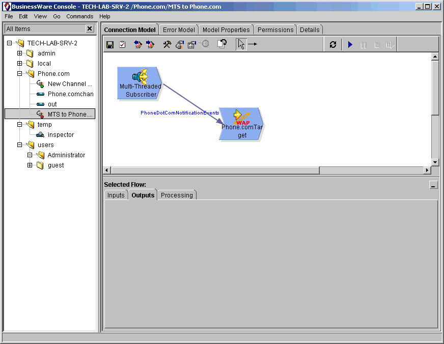
The advantage of using the connection model template is that a multi-threaded subscriber and a Phone.com Target flow are already in position and wired together in the workspace. However, the channel itself doesn't exist; you must either create the channel, or you must enter the name of an appropriate channel that already exists in the namespace.
A channel must exist before the connection model can run. (If you are incorporating the Phone.com Connector into an existing BusinessWare application, you may not need to create a new channel. Just be sure you set the Channel name property in the Multi-threaded Subscriber to the correct channel name, including the folder in the BusinessWare namespace; see 2.3.2 Configuring Multi-threaded Subscriber Flow Properties for information.)
The next series of steps guides you through creating a channel:
Each flow in a connection model is a software component that is configurable prior to runtime. The properties are contained in the Flow Properties sheet. All BusinessWare flows have some basic properties that can be set; for example, every flow has a log level property that can be set to determine how much logging information should be saved for the flow.
In addition to common properties such as this, every flow type has its own unique properties based on its specific functionality. For example, the Phone.com Target flow sends messages to a WAP gateway for ultimate transmission to a WAP-enabled device. The properties for this flow that are specific to this functionality include host—where to send the messages; and character set—how to display the messages. (See Configuring the Phone.com Target Flow for complete properties list.)
2.3.0 Accessing a Flow's Property SheetWith a connection model displayed in the workspace, you can access the property sheet of any component (flow) in one of several ways:
You can use any of these approaches to select and configure the flows in a connection model. |
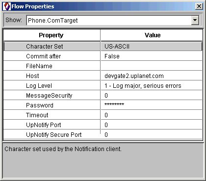 | In a production environment you should always enable the security settings for the connector by changing message security to 1 or 2 and by providing the necessary certificate and a password. (As shown here, security is not enabled.) See MessageSecurity, FileName, and Password usage notes in Table 2.3.1. |
For testing purposes, you can leave the default values alone (as long as you provision a subscriber account at Phone.com and use the developer's UP.Link Server at devgate2.uplanet.com.) The defaults provide no security; in a production environment, you will likely want to create and distribute certificates and passwords. See the Description column in Table 2.3.1 for additional information about the flow's properties.
| Property | Description | Defaults |
| Character Set | Specify the character set for notifications. Determines how messages will display on wireless device. | US-ASCII |
| CommitAfter | Transactional semantics have not been implemented in the Phone.com connector flow at this time; leave this at the default value of False. | False |
| FileName | This setting is for certificate-based security. Enter the filename for the certificate that will be sent with the request at runtime. The file must be generated by a valid CA (certificate authority), such as Verisign (or any other supported by Openwave). | |
| Host | The default value, devgate2.uplanet.com, is the name of the WAP gateway hosted for developers on Openwave's Phone.com Developer Web site; this default assumes you have provisioned a test subscriber account at Phone.com. In a production environment, you should change this value to the appropriate host name or IP address of the actual UP.Link Server providing WAP gateway services. | devgate2.uplanet.com | Log Level | Default log level of 1 logs major errors only. Set the log level to a higher value (2,3, 4, or 5—) to increase the amount of data saved to the connector logs; for example, 2 logs warnings, 3 logs all major occurrences, including administrative changes and startup; 4 logs all system occurrences; 5 is the most verbose and should never be used in production environments. | 1 |
| MessageSecurity | Default value of 0 means security is not enabled. Change to 1 for a setting of "security-preferred," or to 2 for a "absolute security." In the security-preferred mode, the connector attemps to connect to the UP.Link Server secure port; if the secure port is not available, it will connect to the non-secure port and deliver the notification. In the absolute-security mode, the connector will only deliver a notification to the secure port, which means if the secure port is not available, the notification won't be delivered. Security-preferred can therefore guarantee delivery (at the price of lower security), while absolute-security cannot guarantee delivery (but is more secure). | 0 |
| Password | Enter the password that accompanies the FileName for the certificate-based security. If you haven't enabled security features, leave blank. | |
| Timeout | The default of 0 means no timeout period. | 0 |
| UpNotify Port | Leave at 0 to specify that communications to UP.Link Server should use the default non-secure port (TCP destination port 4445) on the UP.Link Server, or specify the actual port number on the UP.Link Server (if other than the default has been configured on the UP.Link Server). | 0 |
| UpNotify Secure Port | Leave at 0 to specify that communications to UP.Link Server should use the default secure port (TCP destination port 3356) on the UP.Link Server, or specify the actual port number (if other than the default has been configured on the UP.Link Server.) | 0 |
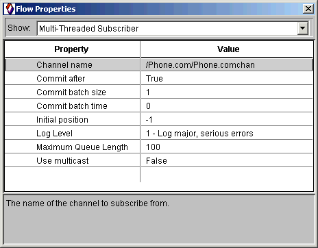
The source of events for the Phone.com Target flow is a multi-threaded subscriber flow, configured to subscribe to events from a specific channel. By default, no channel is specified. You can leave all other default properties as they are, however, you must provide an appropriate channel name.
Note that the multi-threaded subscriber flow is provided by means of the template, but you can also use a Channel Source flow if you prefer. If you will not be implementing multi-instancing of the connection model, there's no need to use the Multi-threaded Subscriber flow.
| Property | Description | Defaults |
| Channel name | Enter the fully-qualified name (in the context of the BusinessWare namespace) of the channel to which you want to subscribe. For example, to subscribe to events on a channel named "Phone.comchan" in a folder named "Phone.com," you would enter /Phone.com/Phone.comchan in this field. | |
| Commit after | Messages picked up from the Channel Source are delivered once and only once, commit after flag set to true so that the message is guaranteed. Leave default setting as is. | True |
| Commit batch size | Commits after every event; leave at default. | 1 |
| Commit batch time | Amount of time (in seconds) to wait before the flow will call commit (if fewer than the quantity of events specified in batch size property has been processed). The default of 0 means that no timer is used. | 0 |
| Initial position | Initial position in the channel to connect to; a value of 0 represents the start of the channel, and a value of -1 represents the end of the channel. | -1 |
| Log level | Default of 1 logs only serious errors. | 1 |
| Maximum queue length | Maximum number of events that can enqueue for this subscriber. | 100 |
| Use multicast | Specifies whether or not the subscriber is multicast enabled. | False |
The PhoneDotComNotificationEvents interface handles eleven different Phone.com notifications. Ten of these event types are sent to the UP.Link Server; the last, SendResult, is generated by the Phone.com connector flow based on data sent back from the UP.Link Server. See Appendix A: PhoneDotComNotificationEvents for details about the events sent by the Phone.com Target connector. These events are discussed briefly in the next section.
The format of the sendResult event is shown in the table.
| Format of the sendResult Event | |
| sendResult | in string oper, in string sub, in boolean result, in long status |
Notifications sent with getStatus() return a different value—0,1,2,3, or 4—depending on the information requested. See the table for a description of each of the values.
| Method | Status | Description | CNtfnStatusNone | 0 | A dummy, invalid status type, which you can use for catching errors. |
| CNtfnStatusPending | 1 | Notification in process of being delivered. |
| CNtfnStatusDelivered | 2 | Notification was delivered to phone. |
| CNtfnStatusExpired | 3 | Notification expired (exceeded the notification's TTL). |
| CNtfnStatusUndeliverable | 4 | Notification could not be delivered. |
You can add another channel target to the connection model to receive sendResult events and take additional actions based on the results. If you want to continue processing in a connection model based on the status of the event, you must decode the sendResult event to obtain its status (from 0 to 4). (See Openwave's documentation for more information about notifications; specifically, see the ENtfnStatus class.)
-DJINTEGRA_NATIVE_MODE -Xms16m -Xmx64m -Xnoclassgc
For example, the Inspector (which you may want to use for debugging and testing purposes) is not multi-instance-enabled. If you add an Inspector (or other non-multi-instance-enabled flow) to the connection model, the model will run in single instance mode regardless of how many instances you have configured.
You are not required to use multi-instancing, nor are you required to use the multi-threaded subscriber flow with the Phone.com connector. You can use a channel source flow instead.
See the Connection Modeling Guide for additional information about the Multi-threaded Subscriber Flow and multi-instancing.
When you create a new instance of the connection model using the template, a default Error Model is also created. Click on the Error Model tab above the BusinessWare Console workspace to display the error model. The default error model contains two flows, an EventLogger flow and a StopOn_Phone.com Target flow. Double-clicking on each of these flows displays a Flow Properties sheet. The properties and default values for these flows are listed below, in Table 2.4.2 and Table 2.4.3.
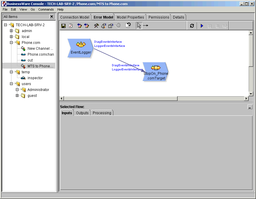
By default, the error model sends events generated by DiagEventsInterface and LoggerEventsInterface to the StopOn_Phone.com flow, which stops the model. Events that don't conform to the selected interfaces are simply passed through the model.
You can leave the default settings as they are. However, you may want to configure the Error Model to take certain action based on different inputs. You can do this by clicking on the StopOn_Phone.comTarget flow in the error model and then clicking on the Processing tab in the lower portion of the Console, below the workspace. The Processing Tab, shown in the screenshot below, displays.
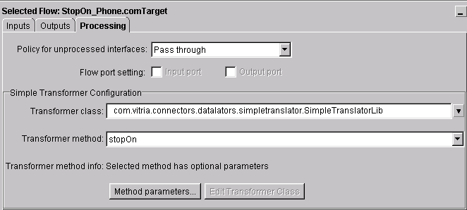
As the screenshot shows, the StopOn_Phone.com flow has been preconfigured to use a method from a transformer class, specifically, the StopOn method. You can change the processing settings according to you needs. For example, you might want to stop the model if events of a particular type enter the error model. You can also pass parameters to the method, as follows:
PhoneDotComConnector, trace-message-name
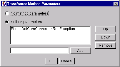
Table 2.4.1 lists method parameters that you can pass to the StopOn_Phone.com flow.
| Parameter | Log Message |
| NotificationFail | Could not send the Notification. Ensure Event Notification is properly configured and event channel (or channels, if more than one) is available. |
| PostAlertFailed | Failed to Post the Alert Notification to Subscriber %s@0. |
| PostPrefetchFailed | Failed to Post the Prefetch Notification to Subscriber %s@0. |
| PostCacheOpFailed | Failed to Post the CacheOp Notification to Subscriber %s@0. |
| PostAlertAndInvalURLFailed | Failed to Post the AlertAndInvalURL Notification to Subscriber %s@0. |
| PostWMSMessageFailed | Failed to Post the WMSMessage Notification to Subscriber %s@0. |
| PushAlertFailed | Failed to Push the Notification to Subscriber %s@0. |
| GetStatusFailed | Failed to Get the Status to the Subscriber %s@0. |
| DeleteFailed | Failed to Delete the notification of the Subscriber %s@0. |
| ClearPendingFailed | Failed to Clear the Pending notifications of the Subscriber %s@0. |
| RemoveAlertFromInboxFailed | Failed to Remove Alert From Inbox of the Subscriber %s@0. |
| ProtocolError | Error in sending the request. %s@0 |
| UnKnownHost | The remote server returned a UnKnownHostException with description %s@0. |
| IOException | There was some communication problem. Server returned with %s@0. |
| CommunicationException | There was a communication problem. Server returned with %s@0. |
| RunException | There was a Runtime problem. Server returned with %s@0. |
The next two tables show the default properties of the EventLogger Flow and the StopOn_Phone.comTarget flow.
Table 2.4.2 provides descriptions of all EventLogger flow properties and the default values. Typically, you will not have any need to change these values.
| Property | Description | Defaults |
| Log file name | The default entry is blank, which means that all messages related to connectors will be appended to the container server log (ContainerServer.log). Leave the default blank, unless you have reason to send messages to a different logfile—in order to troubleshoot a specific problem, for example. | |
| Number of backups | By default, no log files are saved. You can change the default of 0 from 1 to 36 to keep up to a maximum of 36 backup log files. | 0 |
| Size of the log file | Size of log file, in bytes. If you changed the log level to something other than the default of 1, you may want to increase the size of the log file. | 100000 |
The StopOn_Phone.com Target flow has only one property, log level, as shown in Table 2.4.3.
You can change the log level to a higher setting (up to 3 or 4, without incurring performance overhead) to obtain more information during processing. See Table 4.2 for additional information about log level settings.
| Property | Default | Usage Note |
| Log level | 1 | The default of 1 logs severe errors only. |
In addition to changing property settings for the flows in the connection model, you must also configure the event interfaces for each flow and decide how the flow should process events, as discussed in the next section.
The components of a connection model use interfaces to pass events to other components of the connection model and to pass events to channels. You must identify the interfaces that the flow can process and specify how the flow should handle them; in addition, you can specify how a flow should handle events that don't conform to the configured interfaces. Event handling is configured by means of three tabs—Inputs, Outputs, Processing—that display when you click on a particular flow in a connection model in the workspace:
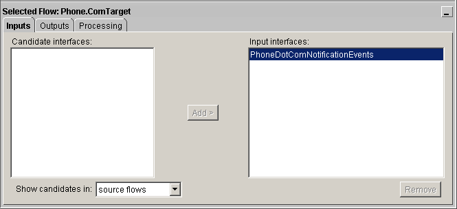
You add (or delete) interfaces on both the Inputs and Outputs tabs in a similar way, as follows:
To remove an interface from either the Input interfaces or the Output interfaces pane, simply click on the interface name and then click the Remove button; the Remove button only becomes active if an interface has already been added.
In addition to defining the interfaces that a flow can receive (inputs) or send (outputs), you must also specify how the flow will handle events that do not conform to the selected interfaces.
The default settings for the Multi-threaded Subscriber and the Phone.com Target flow that comprise the template connection model are shown in Table 2.5.1 below. (The multi-threaded subscriber flow is a source flow only, so by default, it doesn't have any input interfaces available.)
By default, the PhoneDotComNotificationEvents interface is already set as an Input interface for the Phone.com Target flow; however, you must add this to the Phone.com Target's outputs, as well as add it to the Channel Source outputs.
| Channel Source | Phone.com Target | |
| Inputs | Input interfaces | none | PhoneDotComNotificationEvents |
| Outputs | Output interfaces | none | none |
| Processing | ||
| Policy for unprocessed interfaces | Pass through | Pass through |
| Transformer class | na | na |
| Transformer method | na | na |
The flows that comprise the Error Model must also be configured for event handling. Table 2.5.2 lists the default settings for the flows in the connection model template. As the table shows, the StopOn_Phone.com flow has been preconfigured to use a method from a transformer class, specifically, the StopOn method. In general, you can change the settings for the translation class and method as follows:
In addition, you can pass parameters to the method as follows:
PhoneDotComConnector, trace-message-name
The Phone.com Connector implements Vitria's standard internationalized error handling model, in which error, trace, and other text messages are compiled in a resource bundle. You can configure the error model to perform specific actions based specific error messages generated by the connector, including stopping or re-starting the connection model.
| EventLogger | StopOn_Phone.com | |
| Inputs | Input interfaces | none | DiagEventsInterface, LoggerEventsInterface |
| Outputs | Output interfaces | DiagEventsInterface, LoggerEventsInterface |
none |
| Processing | ||
| Policy for unprocessed interfaces | not applicable | Pass through |
| Transformer class | na | com.vitria.connectors.datalators. simpletranslator.SimpleTranslatorLib |
| Transformer method | na | StopOn |
When you finish configuring all connection model components, including event handling, you can save and register the model by clicking the Save and Register Working Copy button on the toolbar (box with checkmark icon).
Whenever you change property values or other settings for the flows in a connection model, you should re-register the model—it's the registered connection model that's used at runtime.
To run a registered connection model, start the connection model by clicking the Start icon on the toolbar. To stop the connection model, click the Stop button.
To change any parameters once the connection model is running, you must stop the connector, make the change, save and register the connection model once again, and then re-start. The complete sequence is as follows:
Vitria provides a testing tool that generates notification events to a channel. Using this in conjunction with the Phone.com Simulator will let you see the connection model in action. Before using the testing software provided with the connector, you should make sure you've got the UP.Simulator working properly.
Here's a brief summary of steps:
After testing the UP.Simulator using the SndNtfn Tool and ensuring that you are able to send notifications over the Internet the Phone.com developer's gateway and have them forwarded to the appropriate subscriber account, you can can test the connection model using the Vitria test tool.
The testing tool is located in the %VITRIA%\java\win32\com\vitria\connectors\phonedotcom\util sub-directory. You can start the Testing application by typing the name of the .bat file:
startclientBy default, the testing program sends events to a channel named "Phone.comchan" in a folder (in the BusinessWare namespace) named "Phone.com" (as shown in the code listing above).
Events will be sent to Phone.com/Phone.comchan
However, you can run the file with an input argument specifying a channel name, as follows:
startclient Phone.com/out
Events will be sent to Phone.com/out
You can also invoke the program using a Java command line, as follows:
java TestWindow Phone.com/out
Events will be sent to Phone.com/out
The name of the channel must be a fully-qualified path in the BusinessWare namespace; that is, including folder names.
The alerts you send from the Test Client are sent through the Internet to Phone.com's WAP gateway. The gateway then encodes the message for WAP transmission and sends it back to the UP.Simulator. You can also view pending and in-process notifications on the gateway (at the Openwave developer's site).
You can observe events as they move through the connection model by inserting an Inspector into the model and then viewing Event History. For complete information about using Inspectors, see the Connection Modeling Guide.
Section 2.0 guided you through the process of configuring the Phone.com Target flow using the template as a starting point. The result of the configuration exercise is essentially a self-contained connection model for a testing or development environment. To use the Phone.com Target flow in the context of a BusinessWare production application, you will need to change several key settings, including:
Security-preferred can therefore guarantee delivery (at the price of lower security), while absolute-security cannot guarantee delivery, but is the most secure option. You must ensure that you make the right choice for the security requirements of your business application.
You can also extend the template connection model to include a channel target. See the Connection Modeling Guide for complete details on configuring and running connection models.
| Symptoms | Solutions |
| Connection model starts but then stops immediately |
1. Check the log file for error messages. See Table 4.2: Log and Error Messages for some common log messages and what they mean. 2. Make sure you registered the model (or re-registered, after making any changes) properly after configuration. See Starting and Stopping a Connection Model for details. 3.Make sure a channel exists and that the multi-threaded subscriber flow is correctly configured for the channel name. See Creating the Channel for details.A channel must exist before the connection model can run; channel names are case-sensitive and must be fully-qualified, such as /users/mobile/Phone.com/phone.comchan. |
| "can't find classname" | Make sure the system CLASSPATH environment variable includes the directory containing the connector's Java classes. On Windows NT, this is the System CLASSPATH, not the User CLASSPATH. | Java: AutomationException: 0x80070005 - General access denied error | Make sure %VITRIA%\jintegra is in System PATH environment variable |
| Java: AutomationException: 0x5 - Access is denied. | Make sure %VITRIA%\jintegra is in System PATH environment variable. |
| Java: AutomationException: 0x80040154 - Class not registered | You will get this error if attempting to use J-Integra to talk to a COM component that is hosted in a DLL. In order to access it, it is necessary to configure a surrogate EXE (because DCOM can only be used to talk to EXEs). See Re-registering the COM-Java Bridge for details. |
The Phone.com software was built using Microsoft's COM (component object model) technology, which means that using Phone.com in the context of BusinessWare (which is Java-based) requires a Java-COM bridging mechanism.
Linar's (Linar Ltd) J-Integra software provides the necessary bridging functionality. J-Integra components are installed and registered during the connector install process.
However, if you have problems with your installation (such as the AutomationException error shown in Table 4.1, for example) you may need to re-register the UPNotify.dll with the Java environment using Linar's command-line tool setdllhost.exe, as follows:
setdllhost pathname\UPNotify.dll "upnotify"
where pathname is the location of the Phone.com UPNotify.dll; this file contains the COM library of notification functions.
Every flow has a log level property; the default value is always 1, which means only severe errors are logged. You can change to a higher level if you like, as long as you are aware of the implications (see Table 4.2 Log Level Settings).
For example, if an error occurs while the connection model is running, you can increase the log levels to capture more information. To do this, you must stop the model, change the log level on the flow's property sheet, and then re-register and re-start the model. You can then examine the logs for additional information about the error message.
Messages from the Phone.com Target connector are sent to the ContainerServer.log file, which is located in the installation directory under %Vitria%\logs\.
Log level settings range from 0 to 5, as shown in the table; log level settings are cumulative.
| Log Level | Description |
| 0 | Logging is not enabled; no errors are logged. |
| 1 | The default value for all flows. Only logs error messages. |
| 2 | Logs error messages and error details; success messages; connection model start; connection model stop; warning messages. |
| 3 | Logs start message for each event; error messages and error details; success messages; connection model start; connection model stop; warning messages. |
| 4 | Logs values of parameters for each event; start message for each event; error messages and error details; success messages; connection model start; connection model stop; warning messages. |
| 5 | Logs values of connector properties; values of parameters for each event; start message for each event; error messages and error details; success messages; connection model start; connection model stop; warning messages. (Don't use this setting in a production environment because performance degrades noticeably. Use only for testing and debugging purposes.) |
This table lists the events and parameters handled by the PhoneDotComNotificationEvents interface.
| Event | Description |
| pushAlert | in string subs, in string url, in string nid, in long ttlSeconds,in string contentType, in string entity |
| postPrefetch | in string subs, in string url, in long ttlSeconds |
| postCacheOp | in string subs, in string url, in long ttlSeconds, in string cacheOpOpcode |
| postAlert | in string sub, in string url, in long ttlSeconds, in string alertType, in string alertTitle, in long titleLength |
| postAlertAndInvalURL | in string sub, in string url, in long ttlSeconds,in string alertType, in string alertTitle, in long titleLength |
| postWMSMessage | in string phone, in string content, in long length |
| getStatus | in string sub, in string url, in long ntfnType |
| delete | in string sub, in string url, in long ntfnType |
| clearPending | in string sub, in string url |
| removeAlertFromInbox | in string sub, in string url, in long ttlSeconds, in string alertType |
| sendResult | in string oper, in string sub, in boolean result, in long status |
Openwave, the Openwave logo, and UP.SDK are trademarks of Openwave Systems, Inc. All rights reserved.
Last updated: 20-Dec-2025 [Defunct]